
Synchronize your machine vision cameras by hardware triggering
To achieve perfect synchronization between all industrial machine vision cameras, you will need the I/O port of the camera. The master camera will hardware trigger its slave cameras, ensuring flawless synchronization between them all. Follow our example to connect one master camera to three slave cameras, creating a perfectly synchronized setup of four machine vision cameras.
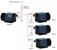
Technical schematic of a synchronized machine vision camera setup:
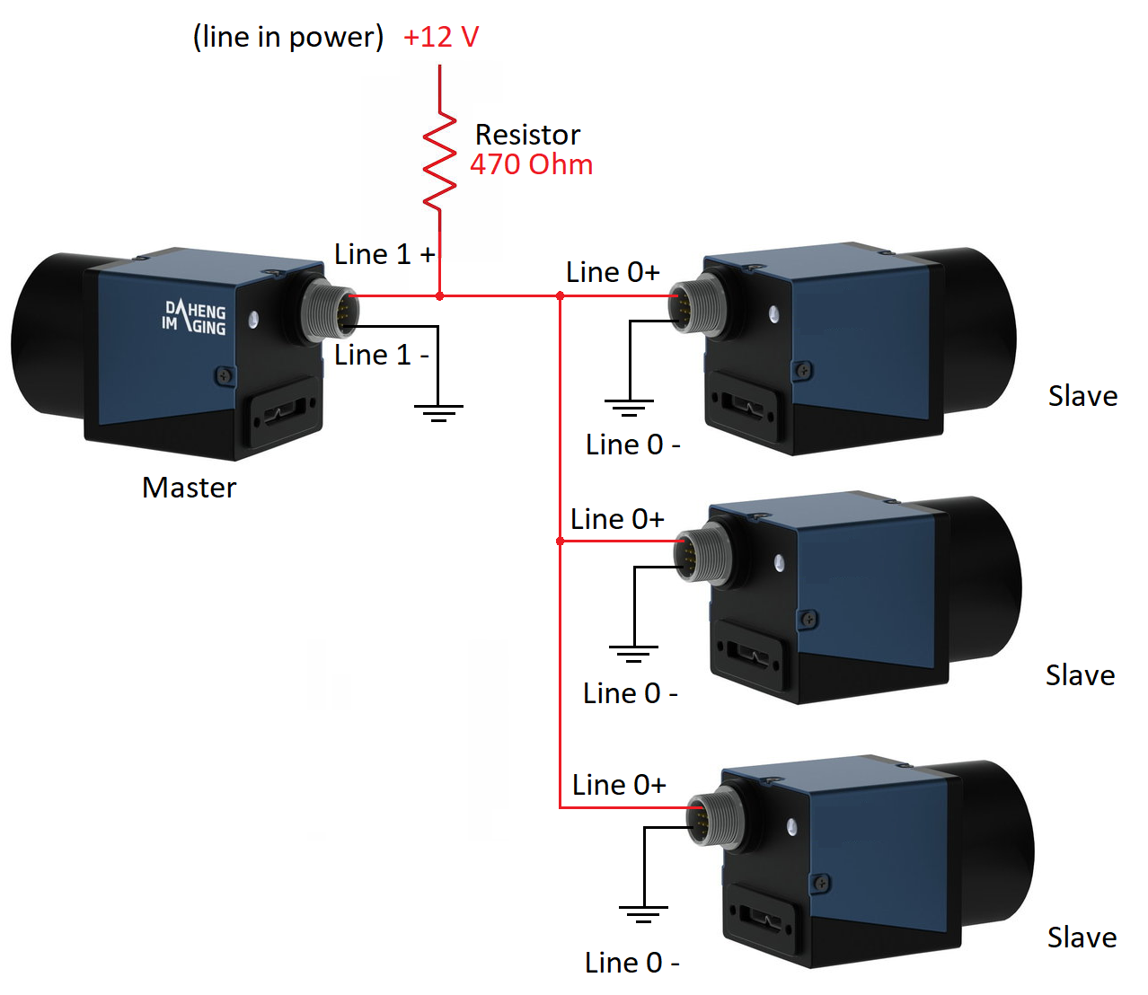
To trigger three slave cameras from one master camera, you will need an external power supply. It is essential to use an external power supply with a voltage range between 5 and 24V for the synchronized camera setup. In our example, we will use a 12V external power supply. The power Line 1 output can withstand 25 mA max. A Line 0 input(s) requires 7mA to work. Therefore, the master camera can trigger a maximum of three slave cameras (7*3=21mA) using the slave cameras trigger input Line 0.
If you need to synchronize more cameras (or have another question), please contact us to explain you how to use the other I/O available to synchronize a maximum of 10 industrial cameras. Check out the technical schematic of a synchronized camera setup below.
Calculation of resistor to limit the current for the synchronized machine vision cameras
To protect the machine vision camera electronics and ensure smooth operation, it is essential to use the right resistor value based on the external power supply voltage and the number of slave cameras connected.
For instance, in our example, we are synchronizing three slave cameras with one master camera using a 12V external power supply. To calculate the resistor, you can use the formula Resistance = Voltage / Current (I), where the current ranges from 7 to 25mA depending on the number of slave cameras connected.
1 slave camera -> current between 7 and 25mA, preferred approx. 12mA
2 slave cameras -> current between 14 and 25mA, preferred approx. 17mA
3 slave cameras -> current between 21 and 25mA, preferred approx. 24mA
To simplify your calculations, we recommend the following resistor values for a 12V external power supply:
- 1 slave camera: 1000 Ohm resistor
- 2 slave cameras: 680 Ohm resistor
- 3 slave cameras: 470 Ohm resistor
In our schematic, we have three slave cameras, so we use a 470 Ohm resistor to synchronize a total of four machine vision cameras. For more information on how to sync up to 10 machine vision cameras, do not hesitate to contact us.
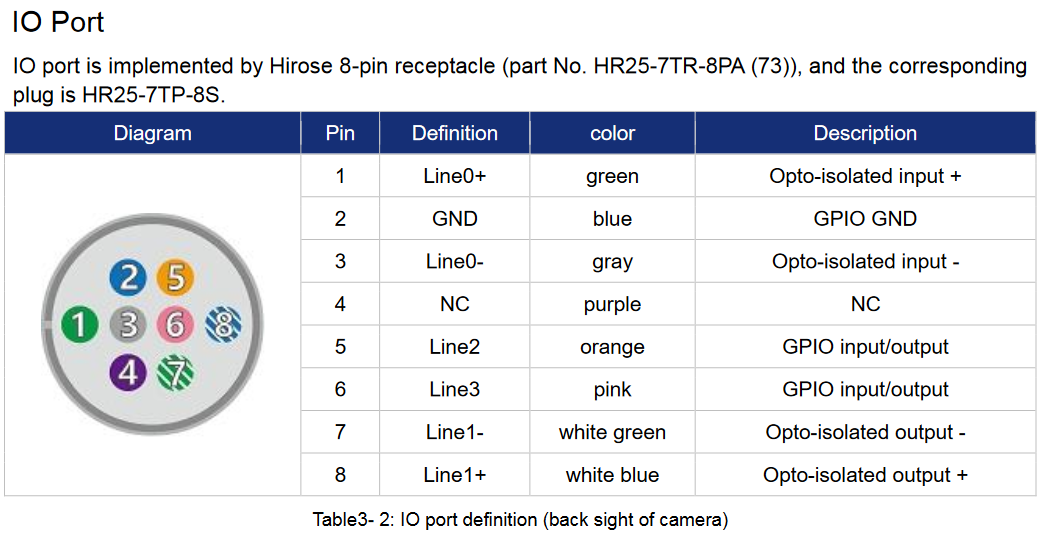
I/O connector to hardware trigger a machine vision camera
The Input/Output (I/O) connector of the machine vision camera is used by the master camera to hardware trigger the slave cameras. The pinout of the I/O connector is:
Programming the machine vision cameras in synchronized camera mode
Programming machine vision cameras for synchronization requires the Galaxy SDK. To ensure that the SDK is installed correctly, follow the five easy steps to install a machine vision camera as explained in our article.
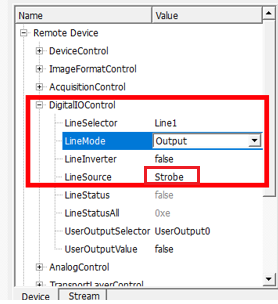
The master camera should be in free-running mode, and every time it captures an image, it makes line 1 output high. Connect to the master camera and go to Menu: Remote device/DigitalIOControl for programming this in your Galaxy Software Development Kit program,. Then, select Line1 and change LineSource to “Strobe”.
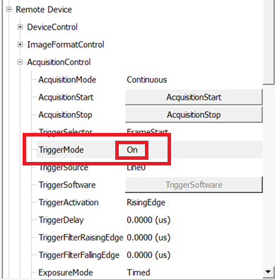
Next, connect to the slave cameras one by one and program them as hardware-triggered cameras with a trigger source of line0. To do this, go to Menu: Remote device/AcquisitionControl, change TriggerMode to “ON”, and TriggerSource to line0. Make sure the other settings are properly adjusted.
are as shown.