


I/O control: Learn to trigger machine vision lighting and to use a trigger sensor for giving hardware triggers to your machine vision camera
I/O control is crucial for effectively triggering machine vision cameras and lights. Industrial machine vision cameras are known for their reliability and robustness, so it's essential to have a dependable external triggering system.
When fast operation is required, the trigger sensor needs to respond quickly. By altering the voltage on the specified pins of the camera's I/O connector, the trigger sensor initiates the triggering process. This triggering system operates based on the rising or falling edge of the voltage, either transitioning from low to high (rising edge) or high to low (falling edge).
Implementing this approach enables the machine vision camera to promptly respond to trigger sensor activations, ensuring swift and accurate capture.
Reach out below or continue reading the article if we could assist you with I/O control.
Setting up the machine vision camera for accepting triggers from the trigger sensor
To enable a machine vision camera to accept triggers from a trigger sensor, you can utilize our Galaxy SDK software. When connected to the camera, follow these steps to program your trigger source:
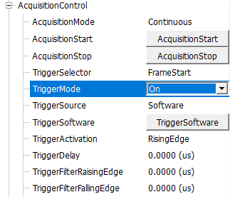
Activate trigger mode by setting “TriggerMode” to “On.”
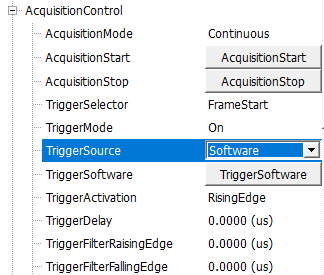
Select the trigger source. Choosing the software option triggers the machine vision camera by pressing the “TriggerSoftware” button.
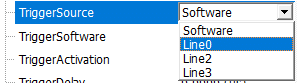
Alternatively, when using a trigger sensor, select the input line where the trigger signal will be received, such as “line0.”
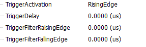
Once these settings are configured, the machine vision camera is ready to be triggered via the input line specified (e.g., line0). For further optimization, you can adapt the trigger settings by defining parameters such as RisingEdge, FallingEdge, TriggerDelay, and TriggerFilters to prevent undesired triggers caused by noise in the trigger signal.
Using the trigger sensor to trigger the machine vision camera
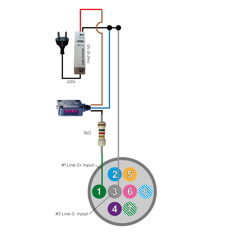
In our schematic, we demonstrate the use of the Retroreflective photo sensor S100-PR-5-C10-PK as the trigger sensor to hardware trigger the machine vision camera. When an object interrupts the sensor's reflected light beam, power is transmitted to the camera's input pin, triggering the camera.
Using a foot pedal to trigger the machine vision camera
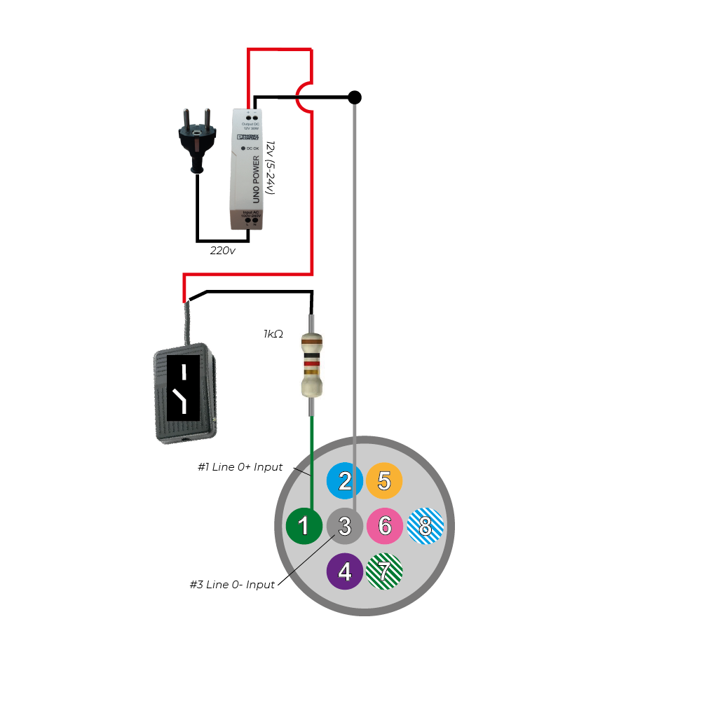
In another schematic, we showcase the use of the Foot Switch FS-01 foot pedal as the hardware trigger for the machine vision camera. The foot switch can be replaced with any analog toggle switch that transitions from open to close.
Triggering of a strobe or light with a machine vision camera
To trigger a light source, you can assign the "strobe" function to one of the camera's three outputs. In our case, we designate Line1 as the output and set the LineSource to Strobe.
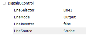
With this configuration, Line1 functions as a strobe output, generating a high voltage signal when all camera pixels are ready to capture light. The signal is low when either none or only a portion of the pixels are prepared for capture.
For global shutter cameras, all pixels are ready to capture light simultaneously. However, for rolling shutter cameras, it takes approximately 1/framerate (e.g., 20ms for 50fps) before all pixels are ready. Consequently, the strobe signal of a rolling shutter camera only works with exposure times longer than 1/framerate.
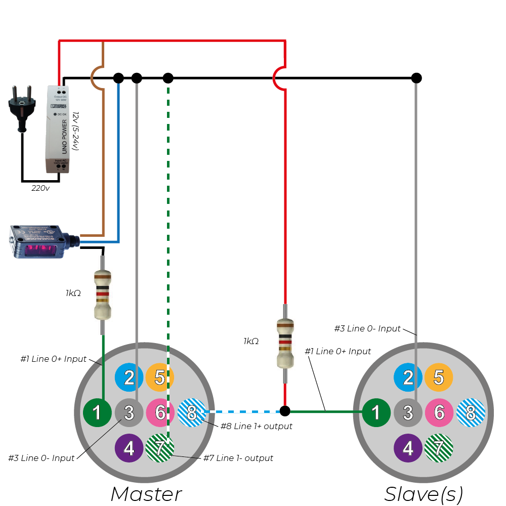
Triggering a second machine vision camera (Master/slave setup)
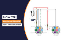
Here is an example of how to set up a MASTER camera triggered by a photocell, with the SLAVE camera synchronized to the master camera.
When the trigger sensor is activated, it generates a high output voltage, which results in a high voltage on input PIN1 of the master camera.
Once a rising edge is detected on PIN1 of the MASTER camera, the camera opens the contact between PIN7 and PIN8 as soon as all pixels are ready to capture light. By default, pins 7 and 8 are normally closed (NC).
- When the contact between PIN7 and PIN8 is closed, it causes a low voltage on both pin 7 and pin 8 of the MASTER camera. Consequently, pin 1 of the SLAVE camera remains low. The current flows from the 24V power source through the 1K resistor (used for current limitation), through pin 8 of the master camera, then through pin 7 of the master camera, and back to the ground of the power supply.
- On the other hand, when the contact between PIN7 and PIN8 is open, the voltage on pin 7 becomes low, while the voltage on pin 8 of the master camera becomes high. This change in voltage also leads to a high voltage on pin 1 of the slave camera. The current flows from the 24V power source through the 1K resistor (used for current limitation), through pin 1 of the slave camera, then through pin 3 of the slave camera, and back to the ground of the power supply.
This setup allows the master camera to trigger the slave camera effectively in a synchronized manner, creating a seamless workflow.
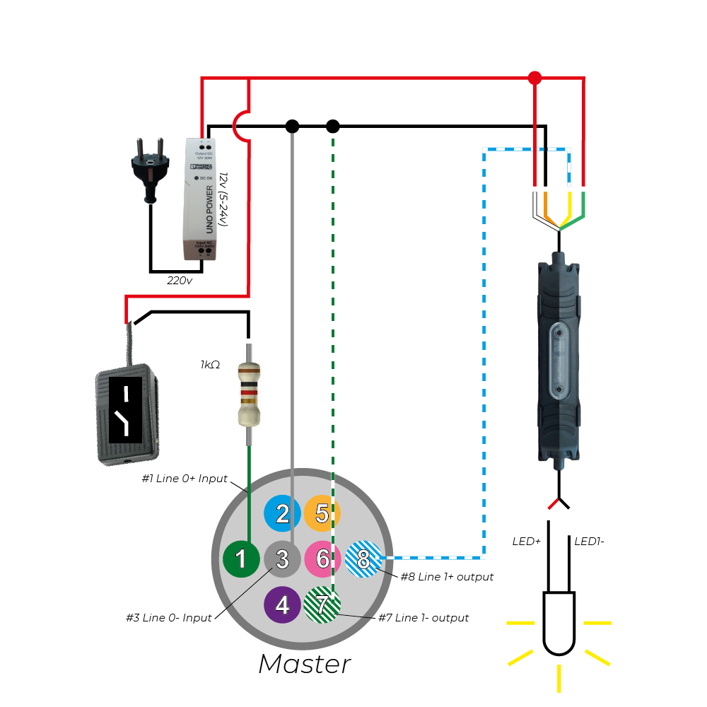
Triggering an external light source with your machine vision camera
In addition to its primary functions, a machine vision camera can also trigger an external light source with the help of our strobe controller. Here is a schematic illustrating how a camera triggers an external strobe controller featuring an LED light. Additionally, an analog pedal switch is connected to enhance control.
I/O port of USB3 and GigE machine vision cameras
It's important to note that the pin-out configuration of a GigE camera slightly differs from that of a USB3 camera. With a GigE camera, there is an option to power the camera using the I/O connector, whereas this capability is not available for USB3 cameras. USB3 cameras rely on the voltage provided by the USB bus to power the camera. However, these differences do not impact the above-mentioned schematics for triggering a camera. To establish a connection using a trigger cable, you will need a trigger cable with an HR25-7TP-8S plug, ensuring compatibility and seamless integration.
Do you have questions regarding the products being used in our examples or need technical support? Continue reading or reach out below, one of our experts will get in touch as soon as possible.
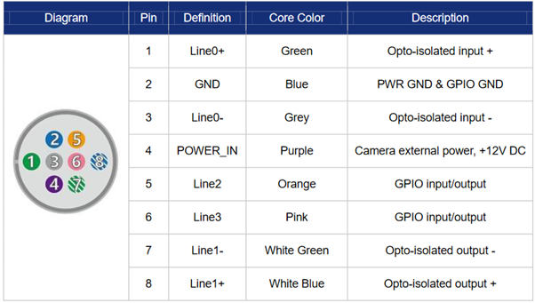
MER2 GigE Camera I/O
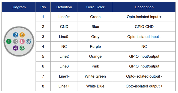
MER2 USB3 camera I/O
Advanced trigger functions
When configuring your machine vision system, we highly recommend utilizing line 0 as the camera input and line 1 as the camera output. These lines offer optical isolation and operate within specific voltage ranges, ensuring reliable performance:
- Logic 0 voltage: 0V~+2.5V (Line0/1 voltage) -> No action is triggered.
- Logic 1 voltage: +5V~+24V (Line0/1 voltage) -> Action is triggered.
- It's important to note that the minimum current is 7mA, while the maximum current is 25mA. To control the current effectively, we suggest using a current limiting resistor above 9V.
Expanding Inputs and Outputs: Utilizing Line 2 and Line 3
If your application requires additional inputs or outputs, you can utilize Line 2 or Line 3. Although these lines lack optical isolation, you can program each line as either an input or an output. Consider the following voltage specifications for Line 2 and Line 3:
- Logic 0 input voltage: 0V~+0.6V (Line2/3 voltage) -> No action is triggered.
- Logic 1 input voltage: +1.9V~+24V (Line2/3 voltage) -> Action is triggered.
- When configuring Line 2 or Line 3 as an input, it's essential to avoid using pull-down resistors over 1K. Otherwise, the input voltage of Line 2 or Line 3 may exceed 0.6V, leading to unstable recognition of logic 0.
- To prevent damage to GPIO (General-Purpose Input/Output) pins, it is advisable to connect the GND (ground) pin before supplying power to Line 2 or Line 3.
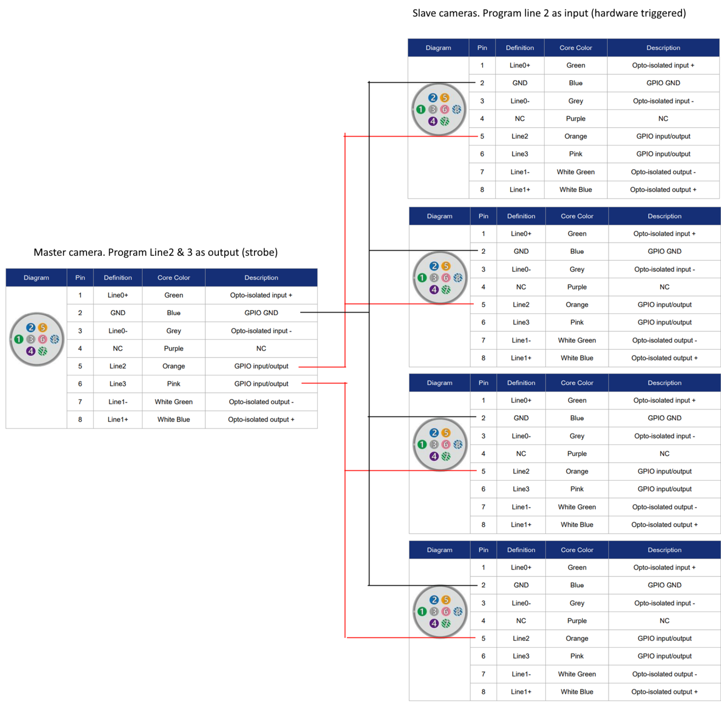
Synchronize multiple machine vision cameras in absence of an external power supply
Achieving synchronization between a master camera and multiple slave cameras is possible without requiring an external power supply. This can be accomplished by configuring Line 2 and Line 3 as OUTPUT. Refer to the schematic below for a better understanding.
Once Line 2 and Line 3 are set as output, they generate a 3.3V output signal, which is sufficient to trigger the slave cameras. In turn, the input line (Line 2) of the slave cameras is configured as an INPUT, detecting a logic 1 input voltage greater than +1.9V.
Implementing this method enables seamless synchronization of multiple cameras without the need for additional hardware.
It's important to consider cable lengths when configuring the system. Since the output voltage is 3.3V, and the minimum voltage required for triggering is 1.9V, it is crucial to keep the I/O cable length as short as possible. Lengthy cables, due to internal cable resistance, may result in voltage drop, causing the received input voltage to fall below the critical level of 1.9V. This can lead to insufficient triggering of the slave cameras.
To address longer cable lengths, we recommend employing an external power supply to increase the voltage output level, ensuring reliable triggering across the system.
Furthermore, hardware trigger does have various characteristics and options to make the setup even more reliable.
Rising/Falling edge delay is the time the camera needs to “confirm” a trigger happened.
Frametrigger wait: The Camera output becomes high when the camera is ready to receive a new hardware trigger. Using this option, you can achieve the highest hardware trigger rate.
Input Debouncer: Rising edge filtering and falling edge filtering, specifies the minimum duration of the pulse to be considered a valid signal. You can filter out noise from the trigger signal to prevent triggers caused by noise.
Trigger Delay: The time between the trigger is confirmed and the trigger action is executed.
Input Inverter: The user can select whether the input level is reverse or not by setting "LineInverter".
Improvement of I/O capabilities: RS232 functionality customized for your machine vision camera
Are you in need of additional I/O functions, such as RS232, for your industrial camera? If your specific application requires special functionalities for the I/O connector of your camera, like utilizing GPIO as an RS232 port, we've got you covered. Our team can create customized firmware tailored to your unique requirements.
Unlock the full potential of your industrial camera by integrating specialized I/O functions. Whether you need RS232 capabilities or other specific functionalities, our experts are here to assist you. Reach out to us today to explore the possibilities and enhance the I/O capabilities of your industrial camera.