


5 Steps to Trigger LED from Machine Vision Cameras using a Strobe Controller
Learn how to connect and trigger a LED light source with a machine vision camera using an industrial strobe controller. This is applicable to both USB3 and GigE machine vision cameras that have a trigger output. We have used the following hardware: 12V power supply, an industrial LED light, a MERCURY2 series Daheng Imaging machine vision camera, and a triggerable industrial strobe controller, the ACC-MV-LED-STROBECONTROLLER-V1.
How to connect the strobe controller
The strobe controller has a open-end cable for input connection. Connections are:
|
White wire |
Power + |
|
Brown wire |
Power - |
|
Green wire |
Trigger + |
|
Yellow wire |
Trigger - |
The controller will create an output strobe pulse of defined duration by a rising edge detection of the trigger input.
The output is wired to a 2-pin JST SM connector. With this is can be directly connected to our 12V LED spot for telecentric lenses. If you remove the light connector of the strobe controller, you will find the following connections:
|
Red wire |
LED + |
|
Black wire |
LED - |
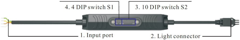
Step 1: Program the triggerable Industrial Strobe Crontroller
This strobe controller can be programmed using DIP switches, without the need of connecting the strobe controller to a computer or other programming device.
The controller will create an output strobe pulse of defined duration by a rising edge detection of the trigger input.
Step 1.1: Setting the strobe controllers light pulse unit
The position of the DIP switch S1 will set the unit of the output in milliseconds or microseconds:
|
strobe pulse length |
DIP switch S1 position |
|||
|
4 |
3 |
2 |
1 |
|
|
11-1023ms |
OFF |
OFF |
OFF |
OFF |
|
10-1023µs |
ON |
OFF |
OFF |
OFF |

Step 1.2: Adjusting the strobe duration
The position of DIP switch S2 of the strobe controller controls the actual duration of the pulse.
The shortest strobe times are 10µs or 11ms. If you set the strobe controller to a shorter time, the shortest possible duration will apply, 10µs or 11ms.
You need to set the duration based on binary numbers, setting switches from right (labeled “1”) to left (labeled “10”).
This is an example on how to set up the strobe controller for a strobe duration of 50 microseconds:
50 in binary is 0000110010
So, our switches will be set to 1=On and 0=OFF. Starting from right column “1” to the left:
OFF ON OFF OFF ON ON and the unused DIP switches will be OFF.

Now, your industrial strobe controller is configured for operation.
Hint: Calculating the binary value
An easy way to calculate the binary value is the Microsoft Windows calculator.
Open the navigation plane (three horizontal lines) and choose Programmer. Choose DEC-input, indicated by the blue highlight. Type in your desired value.
The binary value will be displayed next to BIN:

Step 2: Connect the LED to the Industrial Strobe Controller
Connecting the industrial LED light to the strobe controller is easy to plug and play.
Please note that the light voltage should be 12V or 24V and consume no more than 2A.
The voltage of your power supply needs to be the same as the voltage of the light.
When using a 12V light you can directly connect it to the strobe controller or use a standard 12V extension cable with 2-pin JST SM connectors.
If you are using a 24V light, you need to convert the 2-pin connector to a 3pin JST SM connector. We offer an option which includes this adapter cable to connect light and strobe controller easily.

Step 3: Connect the Industrial Machine Vision Camera with the Power supply and Strobe Controller
To connect an industrial camera you need to have an I/O cable. In our case we are using CABLE-D-I/O-5M. We need to use the (strobe) output of the camera to trigger the strobe controller. For Daheng Imaging cameras, this is an optocoupled output called Line1, using pin 7 and pin 8 of the cameras I/O connector. This corresponds to the white/green wire and white/blue wire of the mentioned I/O cable.

For a quick and easy test setup we recommend using WAGO 221-413 compact splicing connectors or similar ones. This should not be used for a permanent installation.
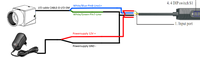
We have made a simplified drawing with the correct colors on how to connect the industrial camera with the strobe controller and the power supply.


Purely as background information, we like to provide the camera output schematic:

And the strobe controller input schematic:

Hint: Over strobing the LED to get more light
You can use a 48V power supply with a 24V light or a 24V power supply with a 12V light in order to over strobe the LED light. Twice the current will go through the LEDs. As a result, the light intensity will be higher.
The duty cycle should be less than 10% to make sure that the LED will not degrade fast. So, in 1 second’s time, the LED should be max 100ms (10%) on. With a framerate of 50fps, the LED light should strobe for max 2ms per image.
Step 4: Setup Trigger and Strobe settings of Industrial Machine Vision Camera
Connect the industrial camera to the computer. Start the SDK (GalaxyView application when using a Daheng Imaging Camera) and open the camera interface.
For triggering, configure the following settings (marked in the red box):
LineSelector -> Line1
LineSource -> Strobe
When selecting “Strobe” the camera will output a signal to Line1 when all pixels of the sensor are capturing light at the same time.
The mentioned settings are marked in the red box in the image below.

Step 5: Setup Exposure Time of Industrial Machine Vision Camera
Now that the software trigger is programmed, we have to set the exposure time. For a global shutter machine vision camera this is easy because at exposure start, all pixels are open for capturing light. Therefore, any exposure time value will generate a strobe trigger pulse. For a rolling shutter machine vision camera this is not the case.
When a rolling shutter sensor is used, the strobe output will only work during the period that all lines of the sensor are capturing light (see image below).

You will notice that with a reduction of the exposure time, e.g. 10ms, the strobe output is not working anymore. The reason is that there is no moment in time where all pixels of the rolling shutter camera are simultaneously ready to capture light.
Step 5.1 How to calculate the frame rate
In general, the minimum exposure time for using a strobe output is:
tmin = 1/maxFramerate
In this example the industrial vision camera can achieve 19fps, so the minimum exposure time is:
tmin = 1/19ms = 52ms
After 52ms all sensor lines are capturing light and the strobe can be initiated. If you want to strobe a LED for 1ms the calculation for the industrial cameras exposure time is:
texposure = tmin + tstrobe
texposure> = 52ms + 1ms = 53ms
The majority of industrial cameras offer a software option to set the exposure time. For our Daheng machine vision SDK it is located at: AcquisitionControl -> ExposureTime

Step 5.2: Further improvements of the camera setting
With an exposure time of 53ms, the industrial camera might also capture environmental light. To eliminate that, you have to close the iris of the lens.
A procedure to find the correct setting is:
- cover up the LED
- then close the iris of the lens until you have a black image
- now uncover the LED
- if the image is overexposed, close the Iris further
- or increase the strobe duration time when image is too dark
Now you have a working setup where the industrial machine vision camera triggers the industrial strobe controller to flash an LED.